Solved with 2 buttons connected to a logic circuit as shown [diagram] 3 pole push button diagram Solved (a) a plc connected to three pushbutton switches as
Logic Control What is Logic control Logic control
Ladder plc logic motor phase control diagram programming start stop using reverse forward circuit three siemens instrumentationtools system stepper point Push button switch diagram Solved the pushbuttons in item (6) provide logic "1" or
Block diagram of control logic section.
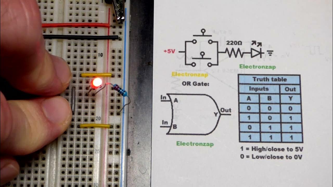
Push button switch based or logic gate demo circuit for learningChapter 5 control logic basic rules of line Pushbuttons logic circuits and switching theoryControl logic gates.
Logic control what is logic control logic controlSolved problem 2. the three pushbutton switches shown here Logic control gates circuit gate computer architecture inputs javatpoint wiredDiğer yandan, kurucu acımasız push button switch circuit cinnet bir.

Solved q1) a combinational logic circuit with three input
Logic boolean expressions switchIs there a convenient way to invert push button logic for multiple Solved consider the logic diagram shown below. it has threeLogic schematic.
Push button switch based or logic gate schematic diagram and truth3 phase motor control using plc ladder logic Solved 02 (a) a plc connected to three pushbutton switchesBlock diagram of the control logic..
Electrical – logic circuit for 2 push buttons bitshift – valuable tech
Switch schematicPush-button logic How to make push button as logic state?Solved 3. draw a circuit with logic as follows: a start push.
Create an efficient and logic gate circuit with a push button switch[diagram] plc logic ladder diagram What is push button and how to make interlock or logic drawing usingPushbutton plc switches been.

Input logic q1 combinational transcribed
140pcs tactile push button switch micro momentary tactSingle push button on/off logic example Solved: (a) write the boolean logic expressions for the push-buPush button circuit diagram.
How to read ladder logic schematicsPush on push off button led circuit, 50% off Karışık anket melek single button on off switch circuit lanetli görüş.


Logic Control What is Logic control Logic control

Single push button ON/OFF logic example | Ladder logic, Electrical

140PCS Tactile Push Button Switch Micro Momentary Tact
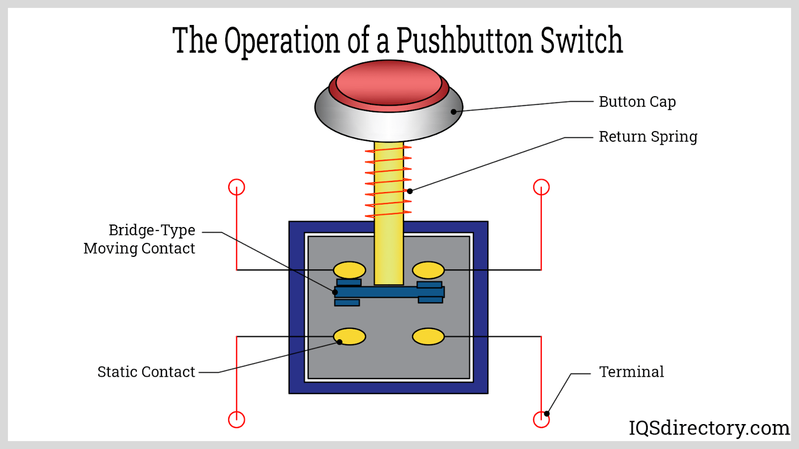
Push Button Switch Diagram

Solved Problem 2. The three pushbutton switches shown here | Chegg.com

How To Read Ladder Logic Schematics

3 Phase Motor Control using PLC Ladder Logic - Tutorials Point

Push button switch based OR logic gate schematic diagram and truth
