Pi&d for the level control loop with the mps pa compact workstation Level control loop methods for industry Level control loop diagram
Purpose of Loop Diagrams - Instrumentation Design
Instrumentation loop diagrams Loop diagram software instrument cad electrical instrumentation manager autocad hook plant diagrams production format automated Instrumentation loop diagrams
[diagram] kaizen loop diagram
House light circuit diagramWhat is an instrumentation loop diagram? Elon musk: the future we're buildingInstrument loop diagram basics.
Industrial instrumentation and control: basics of a control loopElectrical wiring diagram questions Basics of a control loop control valves, control system, feed forwardHook up drawing for pressure transmitter.

Loop diagram instrument instrumentation drawing diagrams cable ild field transmitter create sample marshalling pressure functional single details mounted card
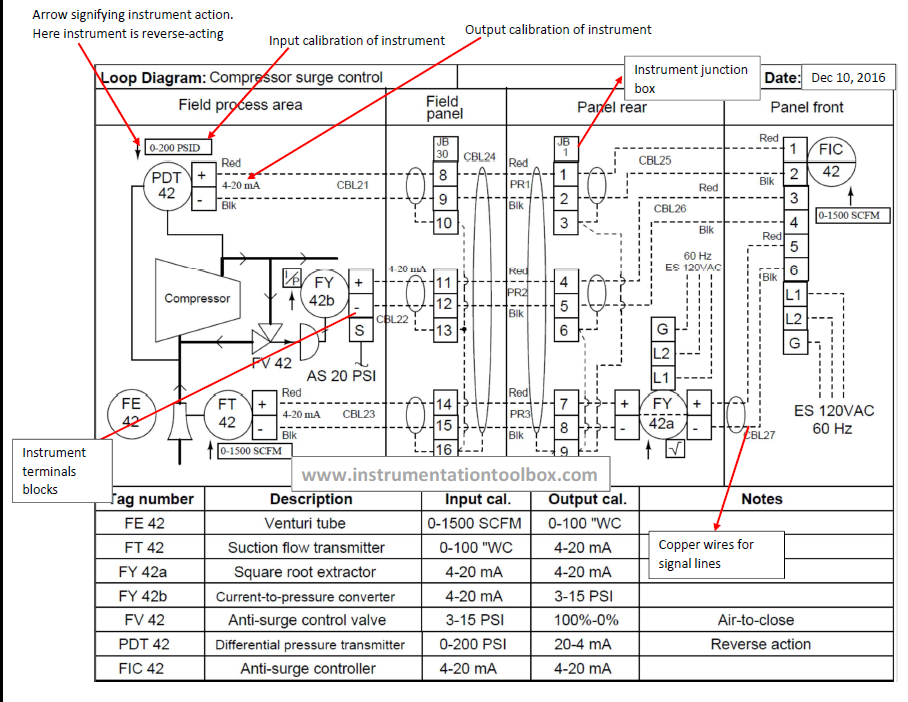
Process control loop diagramInstrument loop diagrams Drawing hook transmitter instrument level pressureLoop wiring diagram instrumentation pdf.
Instrumentation dcs instrumentationtoolsPiping and instrumentation diagrams tutorials on flow and level control Loop diagram instrument instrumentation basics numberLevel controller tuning.

What is loop wiring diagram
Loop diagram instrumentation control field instrument plc wiring electrical sections sample scada room industrial left right divided organize information intoElectrical wiring switch loop Prt 140: lesson 8 introduction to control loops – mining mill operatorPrt lesson loops component controlled pv millops uaf.
An125: tuning level control loopsMps workstation Level control loop diagramSchematic of a level control loop featuring manipulation of the outlet.

How-to create instrument loop diagram?
Plant instrumentation & loop diagram design softwareControl loop diagram Loop in wiring diagramPurpose of loop diagrams.
Instrument loop diagram pumpsLoop wiring diagram instrumentation pdf Speed control open loop system wiring diagramControl loop diagram process basics system instrumentation engineering point industrial valves systems consider electrical article variables maintain set.

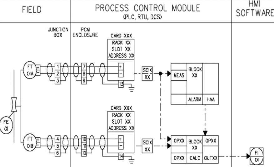
Process control block diagram / process control block (pcb)
Control loop diagram instrumentation industrial basics consider following letLevel control loop methods for industry .
.

Hook up drawing for pressure transmitter | Hook Drawing at channelone

Process Control Loop Diagram

Control Loop Diagram
What Is Loop Wiring Diagram - Wiring Diagram

Level Control Loop Methods for Industry - Equilibar

Process Control Block Diagram / Process Control Block (PCB) - cook the

Instrument Loop diagram basics | Instrumentation
