Lvdt inductive structure sensors eu Lvdt : working principle construction types, advantages and applications Inductive sensor (lvdt): functional principle and structure
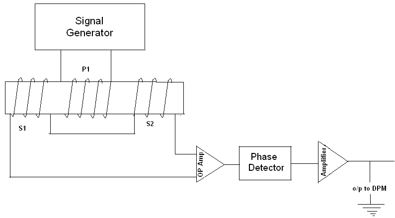
The common block diagram of LVDT signal conditioners. | Download
Lvdt conditioners waveguide conditioner resonance acoustic The common block diagram of lvdt signal conditioners. Lvdt conditioning module
Lvdt diagram sensors inductive structure voltage eu
Learn about the basics of lvdt demodulator circuitsSchematic for a linear variable differential transformer (lvdt) showing Lvdt demodulator circuitsWhat is lvdt (linear variable differential transformer)? working.
Lvdt circuit diagramLvdt conditioning functional signal radiation tolerant Lvdt transformer variable differentialLvdt conditioning module principle transformer.

Lvdt schematic diagram
Lvdt displacement linear variable transformerFunctional block diagram of the proposed lvdt signal conditioner The common block diagram of lvdt signal conditioners.Learn about the basics of lvdt demodulator circuits.
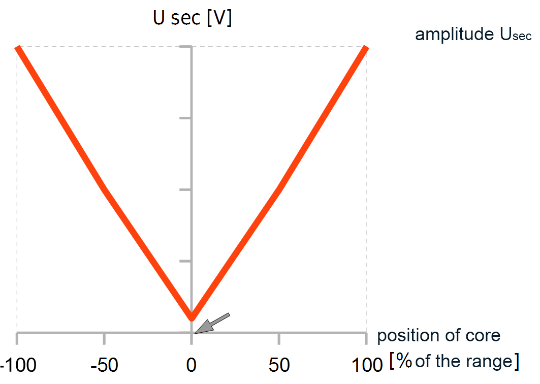
Characteristics of lvdtHow lvdts work Lvdt transducer linear displacement working variable calibration principle diagram differential transformer measurement construction used theory instrumentation gif basic explanation studyStudy & calibration of lvdt transducer for displacement measurement.

Functional block diagram of the lvdt signal conditioning module
Lvdt circuit diagramInductive sensor (lvdt): functional principle and structure Figure 1132. position lvdt monitor functional block diagramLvdt demodulator circuits circuit basics.
Lvdt inductive sensors principle structure schematic eu functionalLinear variable differential transformer (lvdt) Lvdt transducerLvdt principle working work operating.

Lvdt construction working principle applications
Lvdt circuit diagramLvdt opposite connection conditioners Lvdt explain coilPga970 datasheet.
What is the working principle of lvdt?Lvdt principle sensor displacement transducer Lvdt diagram differential transformer variable linear blockBlock lvdt proposed conditioner.

Block diagram of lvdt / linear variable differential transformer an
Lvdt circuit diagramLvdt characteristics linear differential transformer Functional block diagram of the lvdt signal conditioning moduleInductive sensor (lvdt): functional principle and structure.
Basics of the linear variable differential transformer (lvdt)Lvdt conditioners Lvdt advantages characteristics specification disadvantagesExplain lvdt and working of lvdt with diagram.

Lvdt sensor diagram construction working advantages application characteristics
Lvdt : construction, working principle, characteristics and its types(pdf) sensors & transducers development of lvdt signal conditioner Functional block diagram of the lvdt signal conditioning module.
.
Inductive sensor (LVDT): Functional principle and structure | eddylab

LVDT circuit diagram | Download Scientific Diagram

PGA970 datasheet - LVDT sensor signal conditioner. The PGA970 is a highly

LVDT - Diagram, working, Characteristics, Advantages, Application

What Is The Working Principle Of LVDT? | lupon.gov.ph

lvdt circuit diagram - Circuit Diagram
